Installation · Version 1
Version 1 Install Diagram
Installers use this link to test ALL functions after install. This link also keeps you in our database for future installs. (GPS ID is found under the gps and also on the box)
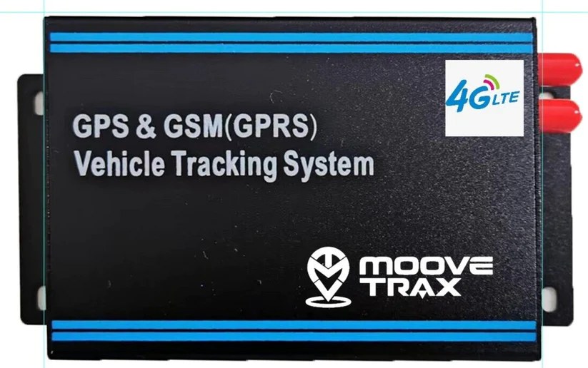
Installer PortalMooveTrax GPS is a system with remote functions: Lock Door (trigger inside button), Unlock Door, Kill Switch, Panic Button. All outputs provide a -ve pulse of 100ma max. We provide a quad relay with its own wiring diagram below.
Devices must be hidden but must stay reachable for the customer to do things like replacing the SIM card.
Wire pinout (10 wires)
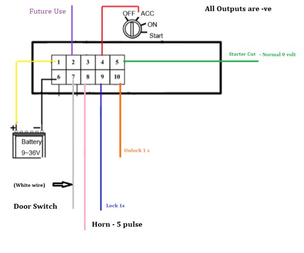
- Yellow -- constant 12V+. (Tell the client which fuse to remove if they want to restart the device.)
- Purple -- smoke detection (optional).
- Ground wire.
- Red -- ACC power 12V+. 12V is sent to this wire when the car is in ACC or running.
- Green -- should control a relay that disables the starter. This is a CONSTANT -ve and NOT a pulse. Only works with ACC on.
- Black -- 2nd ground.
- White -- detects when a door is open. This wire should be grounded to indicate the door is open.
- Pink -- panic signal. Issues five 12V GROUND (-ve) pulses with 1 second between them.
- Blue -- issues GROUND (-ve) for 1 second, used to trigger the door actuator (Lock / trigger interior lock button).
- Orange -- issues GROUND (-ve) for 1 second, used to trigger the door actuator (Disarm -- ensure door unlocks). Double pulse can be set by editing the device from the webpage.
Relay board
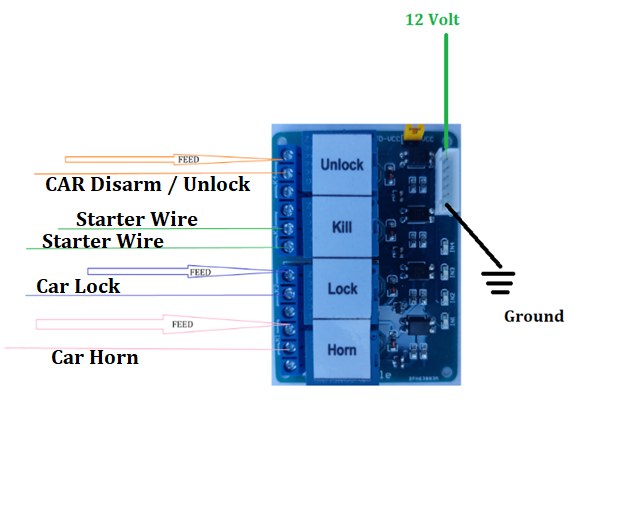
We ship devices with a relay pack. It's usually already set to accept a ground pulse -- in some cases you may need to move the jumper. The relay board is included for convenience; you may use your own relays if you wish. Included velcro is for protecting the underside of the relay board.
Ensure the relay pack white label is not upside down compared to the picture below.
The relay board needs to be powered up separately -- black is ground. FEED is what the wire requires to activate: some functions need a ground, others need +12V.
Newer relays come with one more function after "Horn" -- the function name is "Light." Light gets triggered together with "Horn."
Do not stick the antenna on glass -- glass gets hot to the point the adhesive gets loose.
Signal wiring notes
All signals are analog. If the car sends a digital unlock and lock signal, run the wires directly to the actuator or use a DB3 module.
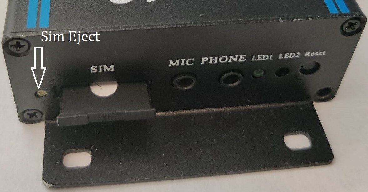
Install the SIM in the device before you power it up.
- * Lock should be wired to the inside door lock button, so a keyless key fob on the interior would not interfere.
- ** Unlock should be wired to the factory alarm disarm wire, so there's no issue when the BCM goes to sleep. If you can't wire to the factory disarm, wire to unlock and turn on "Cycle" during setup to keep the BCM awake.
Please ensure ALL functions work before delivering the car. If all functions do not work, please call MooveTrax at 202-979-TRAX.
Once all functions work, please invite the car owner by entering their email at the bottom of the page and clicking Invite.
Tesla install
- Relay Green wire goes to MooveTrax Green wire.
- Relay Yellow wire goes to Lighter blue wire +12V.
- Relay black wire with pin goes to the black wire removed from the connector.
- Relay black wire with no pin goes to the connector.
- GPS yellow wire goes to connector yellow.
- GPS black wire goes to cig lighter black wire (ground).
- GPS red wire goes to cig lighter yellow wire.
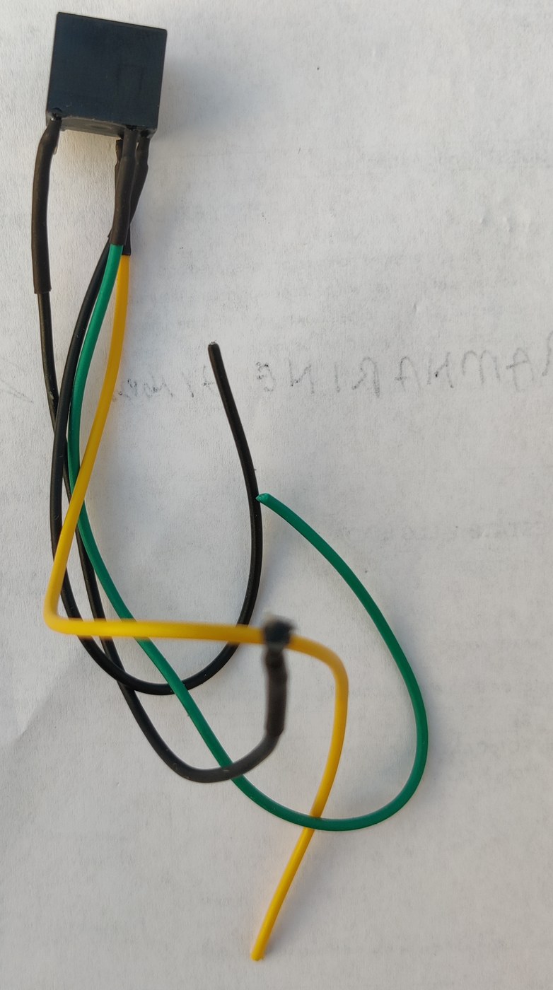
Smoke Detector
The smoke detector we supply is a 5 volt device -- we also supply its power supply.
- We will NOT use the DO (Digital Output) port.
- Analog Output (AO) goes to the GPS purple wire.
- VCC is 5 volt +.
- GND is ground (from the 5 volt supply).
Support
Email: support@moovetrax.com
Phone: 1-(202) 979-TRAX
Installer Facebook group →
Video of how the product works →